Sediment Control
Sediment retention ponds
What, why, when, and issues to look out for
What
A sediment retention pond (SRP) is a temporary pond made by excavating natural ground, or building an embankment, or some combination of the two.
SRPs have an outlet device to dewater the pond at a rate that allows a high percentage of suspended sediment to ‘settle out’ within the pond. This means, to sink to the bottom and stay there as sediment, while the treated, cleaner water is discharged.
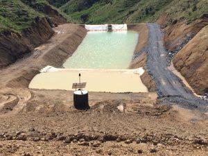
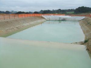
Sediment retention pond in steep hill country, with a flow-activated flocculent dosing system in the foreground (Source: RST Solutions Limited).
Why
SRPs are designed to impound (to enclose and hold back) dirty water. They detain runoff flows so that transported sediment can be deposited by settlement.
Because they also detain water, SRPs attenuate (weaken) water flow, which in turn reduces the potential for channel erosion effects downstream.
When
SRPs are mainly used in the following situations:
- If sediment-laden runoff needs to be treated
- If concentrated flows of sediment-laden runoff occur.
They are the most appropriate control measure for catchments greater than 0.3 ha.
Issues to look out for
SRPs have the following limitations:
- You might need to get specific geotechnical design input.
- Consider the location in relation to ongoing maintenance (especially during winter) and decommissioning at the end of the earthworks.
- You might need specific design details and drawings to make sure that you construct it correctly.
- Restrict catchment areas to 5 ha, to limit the length of overland flowpaths, reduce maintenance and limit the size of flocculent treatment devices.
- SRPs can be a safety hazard if they are not fenced appropriately and if safety rules are not followed. Low gradient pond batters provide an additional safety measure (for access/egress). Check the safety requirements of Worksafe NZ.
- You should also consider treating the dirty water with coagulants and flocculants. SRPs treat dirty water better than many other tools do, but to achieve the water quality outcomes necessary to protect waterways, chemically-enhanced treatment is usually needed.
Design essentials
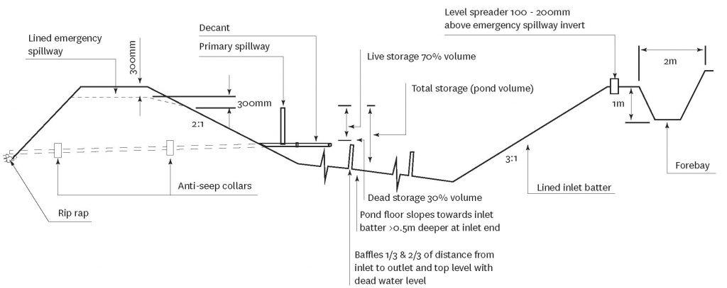
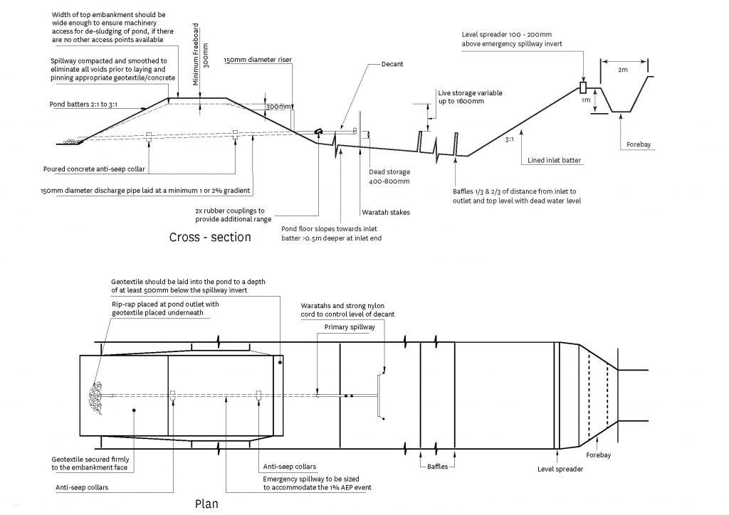
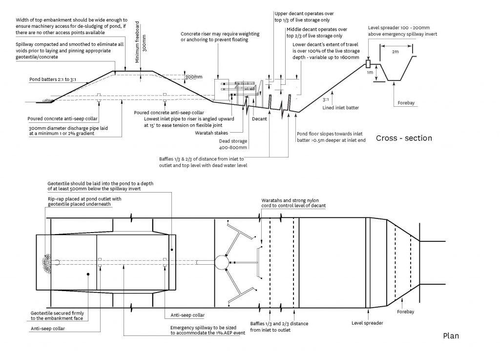
The embankments around SRPs provide the required impoundment volume and shape. Any filled embankment should be no higher than 2.6 m. This height accommodates a maximum 2.0 m pond depth (base of pond to primary spillway), 300 mm freeboard from the primary spillway to the emergency spillway, and a further 300 mm depth of spillway. Going higher than this would increase the overall footprint of the SRP
Size
Size the SRP based on the contributing catchment area and slope length. We have listed the minimal design standards below, but ponds on a number of New Zealand major sites are now built 30% larger than the minimum design values. Experience across New Zealand shows that constructing ponds considerably larger than the minimum is helpful for the following reasons:
- Improved treatment of sediment
- Improved ability to cope with high-intensity storms.
The following calculations define the total storage volume, which is measured from the base of the pond to the top of the primary spillway, and are the minimum standards:
- On earthwork sites with slopes less than 18% and less than 200 m in length, design SRPs with a minimum volume of 2% of the contributing catchment area (200 m³ for each ha of contributing catchment).
- On earthwork sites with slopes over 18% or greater than 200 m in length, design SRPs with a minimum volume of 3% of the contributing catchment area (300 m³ for each ha of contributing catchment).
- The slope angle is determined by the slope immediately (within 20 m) above the SRP or by the average slope over the contributing catchment, whichever is greater. The slope angle should also be the greater of the pre- or post-construction slope.
- If you are planning to batch dose your SRP with coagulants and flocculants, size the SRP to hold all the runoff from the expected design storm. This will mean that your SRP will be considerably larger than if water is being treated ‘online’ or maintaining a flow out as dirty water goes in.
Shape
- Maximise the distance between the inlet and the outlet (including the emergency spillway) to reduce the risk of short circuiting and to promote quiescent (inactive) conditions.
- Make sure that the length-to-width ratio of the SRP is no less than 3:1 and no greater than 5:1. The length-to-width ratio is measured at the height of the primary spillway. The length is the distance between the inlet and the outlet (the decant system).
- The invert must be level to promote the even and gradual dissipation of the heavier inflow water across the whole area of the SRP.
- Building the SRP invert with a gentle reverse slope (deeper at the inlet end) can aid maintenance by promoting heavier sediment to drop out and accumulate at the inlet end of the device.
- For external batter steepness, see SRP plan and cross section designs. For internal batters, we recommend a 2:1 ratio, subject to available space and ground conditions.
Depth
- Depth is measured from the invert to the top of the primary spillway. SRP depths may be 1–2 m only. Ponds deeper than 2 m are more likely to cause short circuiting problems during larger storm events and need specifically designed floating decant systems.
- The decant design in this toolbox has a maximum live storage range of 1.5 m.
Dead storage (permanent storage)
- Dead storage is the part of the impoundment volume that does not decant and stays in the SRP. This storage is important because it dissipates the energy of sediment-laden inflows.
- Keep dead storage at 30% of the total SRP storage by positioning the lowest decant 0.4–0.8 m above the invert of the SRP.
- The decant design in this toolbox allows the lower decant arm to be raised as sediment deposition increases, to maintain the percentage volume of dead storage.
Live storage (decant storage)
- Live storage is the volume between the lowest decant outlet level and the crest of the SRP primary spillway
- The live storage volume capacity should be 70% of the total SRP storage
- The decant design in this toolbox allows the decant arms to be raised as sediment deposition increases, to maintain the percentage volume of live storage.
Forebay
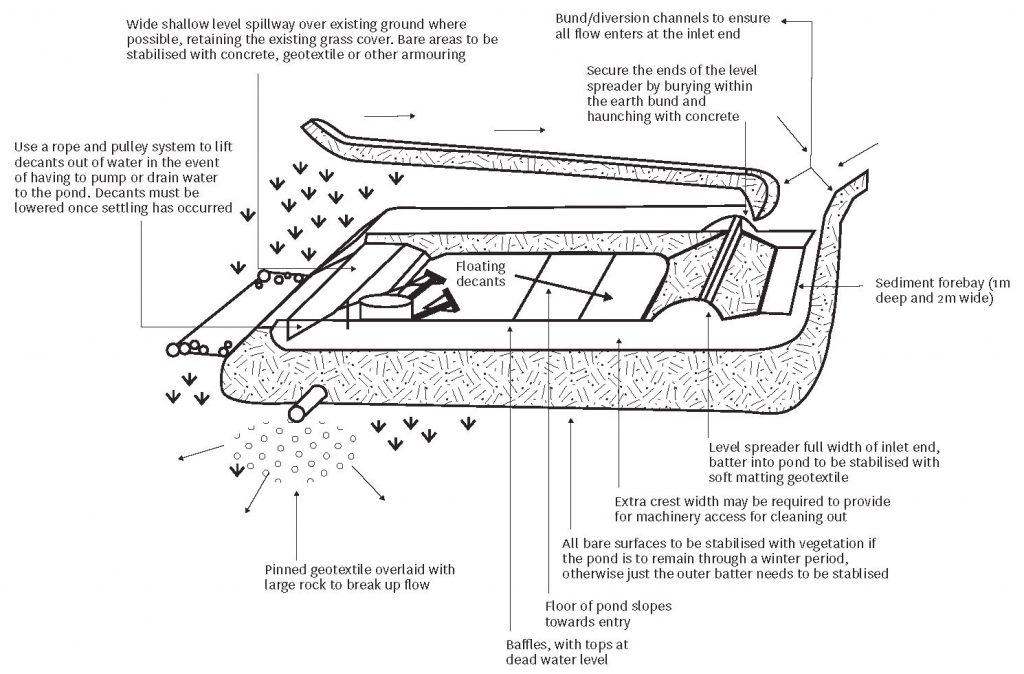
A sediment forebay is an impoundment, basin, or other storage structure designed to dissipate the energy of incoming runoff, and detain the runoff for initial settling of coarse particulates.
Forebays are different from sediment basins because they are usually used to pre-treat runoff before it discharges to the primary water quantity and quality control tool. Forebays are frequently integrated into the design of larger stormwater management structures.
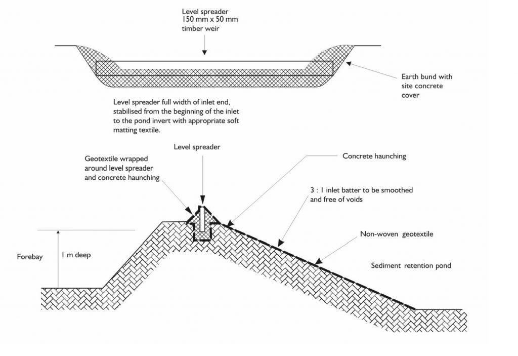
- The forebay should extend the full width of the pond, be at least 1 m deep, and be located upstream of the level spreader.
- Grade the entry to the forebay so that is smooth and even. Likewise, the approach to the level spreader should also be smooth.
Decanting/outlet dewatering device
- The SRP’s decant/outlet dewatering device should be designed to remove water within the upper water column without removing any of the settled sediment, or any significant quantities of floating debris. Use either a 100 or 150 mm diameter decant.
- The floating T-bar dewatering device described in this toolbox allows cleaner surface water to be decanted from the top of the water column.
- The recommended decant rate from an SRP is 3 litres/second/ha of contributing catchment. This rate ensures that appropriate detention times are achieved.
- See standard t-bar decant design which provides a decant flow rate of 4.5 litres/second. Either add decants incrementally to accommodate catchments that are greater than 1.5 ha or restrict the number of holes in the decant to maintain the decant rate of 3 litres/second/ha of contributing catchment.
- T-bars should always be able to float to the top of the primary spillway.
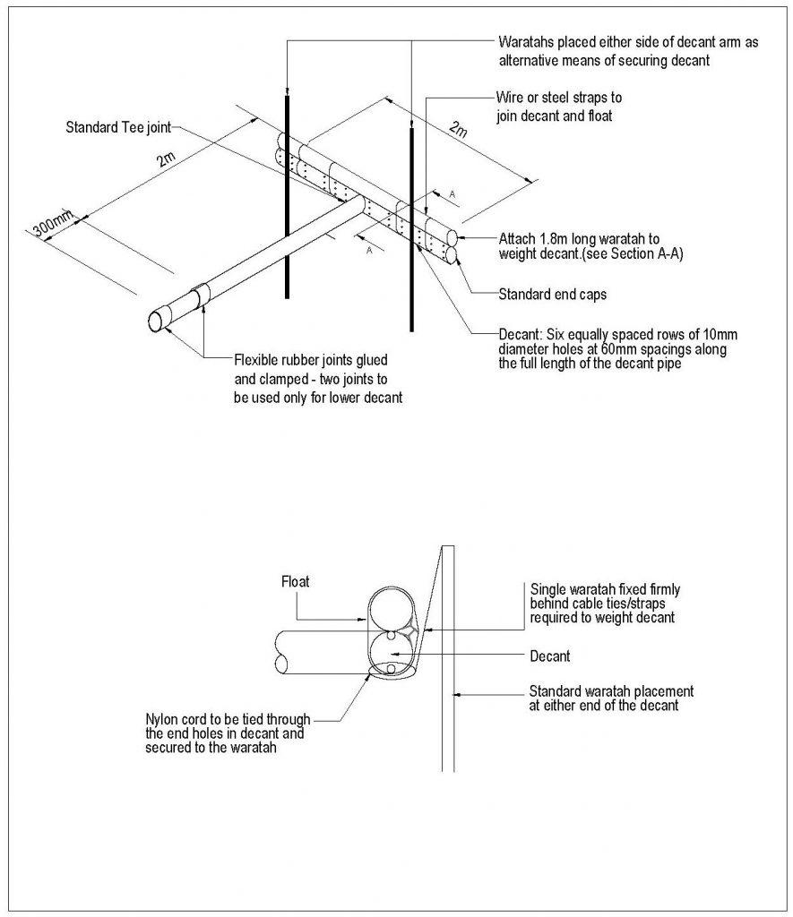
- To achieve a decant rate of 4.5 litres/second per decant, drill six rows of 10 mm diameter holes at 60 mm spacings (200 holes) along the 2 m long decant arm.
- For catchments of less than 1.5 ha, seal off the appropriate number of holes to achieve a 3 litres/second/hectare discharge rate. Try 134 holes for 1 ha, and fewer depending on the catchment size. From 1–1.5 ha, use proportionally more holes.
- Single T-bar decants must be able to operate through the full live storage depth of the SRP.
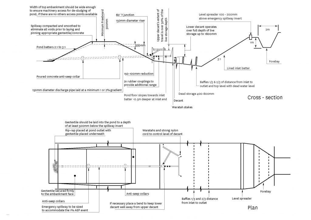
- If you need two decant systems, the lower T-bar decant must operate through the full live storage depth of the SRP. The upper T-bar decant should operate through the upper 50% of the live storage depth of the SRP only.
- If you are using three decant systems, the lower T-bar decant should operate through the full live storage depth and the second T-bar decant through the upper two thirds. The upper T-bar decant should operate through the upper one-third of live storage depth: see figure below.
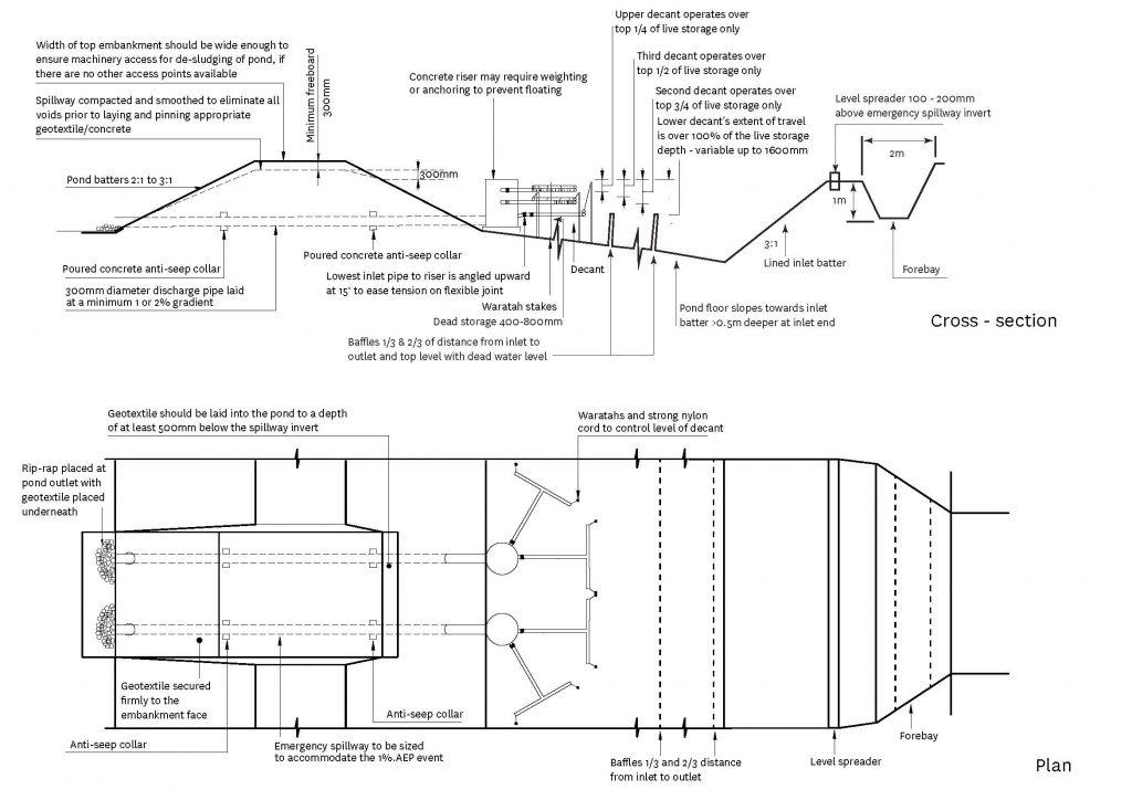
- For large catchments, doubling the decant structures skims off clean water more effectively than single structures with three decanting T-bars. This is because, when the pond is receiving high flows the decant arms can interfere with each other, creating turbulence and disturbing sediment. To solve this problem in large ponds, use two separate outfall pipes with only 2 decant T-bars each. The lowest T-bar of the two systems operates over the full range. The second operates through the upper ¾, the third through the upper ½, and the fourth in the upper ¼.
- For contributing catchments, use the following length of outlet pipe:
- Up to 3 ha, use a 150 mm (minimum) outlet pipe
- 3–5 ha, use 300 mm (minimum).
Primary spillway
All SRPs need a piped primary spillway, which is the vertical upstand or riser pipe that connects to the decant
- For contributing catchments, use the following:
- Up to 3 ha, use a 150 mm (minimum) upstand as a primary spillway.
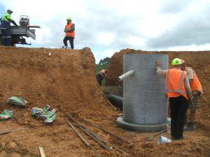
- 3–5 ha, use a 1050 mm (minimum) concrete manhole riser. Consider using 2 risers, so you can have 2 decanting T-bars on each, rather than 3 on a single.
- The primary spillway should be at least 600 mm lower than the top of the SRP embankment and at least 300 mm lower than the emergency spillway crest. Make sure that the riser and the discharge pipe connections are all completely watertight.
Emergency spillway
- All SRPs need an emergency spillway. These must be able to accommodate the 1% AEP event without eroding.
- The emergency spillway level should be at least 300 mm lower than the top of the SRP embankment.
- You need to apply a very high standard of stabilisation to the emergency spillway crest and downstream batter, with well-compacted fill material.
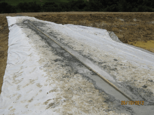
- If you are using geotextile to stabilise the emergency spillway, the batter face must be smooth and all voids eliminated. You will need to cover soft needle punch geotextile with a strong, woven, low permeability geotextile. Pin the geotextile down well with the pins no more than 0.5 m apart over the full area of the emergency spillway.
- Design the emergency spillway as a stabilised trapezoidal cross-section, with a minimum bottom width of 6 m, or the width of the pond floor, whichever is the greater; unless specific design calculations have confirmed that a smaller emergency spillway will accommodate the 1% AEP event.
Baffles
- Install baffles across the width of the pond, at one third and two thirds of the distance from the invert. The baffles should be staked, their top level with the dead water level, and be made of a porous open mesh fabric.
- Don’t install baffles within the pond to try to extend the internal flow length. This creates turbulence, which disturbs and re-suspends sediment.
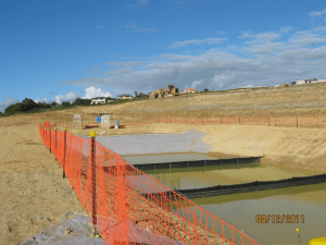
Example of correctly installed baffles, across the width of the pond and at dead water level. Baffles are made of permeable cloth.
Level spreader
- Incorporate a level spreader into the inlet design to reduce inflow velocities and rapid dissipation of inflow energy. The inlet batter downstream of the level spreader must be well compacted and smoothed (no steeper than a 3:1 gradient), and stabilised over its entire area. You must keep the level spreader level, non-erodible and spanning the full width of the SRP.
- To make sure that the inflows are even, install a trenched and pegged 150 × 50 mm timber weir or similar across the full width of the inlet. Secure the ends of the timber weir with compacted earth and a concrete cover to prevent flows outflanking the weir. Install a concrete haunch along the edges of the level spreader to provide added structural strength. This timber weir also serves to toe in any geotextile protection that may be required. You will need to remove sediment that accumulates upstream of the level spreader every so often.
- Position the top of the level spreader weir 100–200 mm above the invert of the emergency spillway.
Anti-seep collar
- Lay the discharge pipe at a 1–2% gradient and surround it with compacted fill. Install anti-seep collars around the pipe with a spacing of approximately 10 m to increase the seepage length along the pipe. The vertical projection of each collar should be 500mm. All anti-seep collars and their connections around the pipe must be watertight.
Flocculent treatment
Most SRPs need flocculent treatment. For more information, see section on Flocculants and Coagulants and Auckland Council’s Technical Publication TP227 – The Use of Flocculants and Coagulants to Aid the Settlement of Suspended Sediment in Earthworks Runoff: Trials, Methodology and Design, June 2004 (PDF 783 kB).
Potential modifications
Field trials and monitoring around New Zealand have shown that changes in SRP design and incorporated in this toolbox deliver significantly improved sediment retention efficiencies. These are now the assumed minimum performance standards for Canterbury. Some additional measures and modifications are:
- Geotextile stabilisation of the SRP’s internal batters.
- Floating booms to reduce wave propagation and reduce maintenance to prevent blockage of T-bar holes by floating (organic) debris.
- Using additives other than PAC. Each project should investigate and use the best practicable option for coagulation and flocculation, at the safest dose for the receiving environment.
Construction and operation
- Form clean water diversion bunds to isolate the SRP construction area.
- Install a silt fence or other appropriate sediment control below the construction area.
- Clear areas under proposed fills of any topsoil or other unsuitable material.
- You might need to key in large fill embankments. Make sure that you build the embankments to appropriate engineering design standards.
- Use only certified fill.
- Place and compact fill in layers to the engineer’s specifications.
- Construct the base of the SRP with a reverse slope so that heavier sediment drops out and accumulates at the inlet end of the device. This will help with maintenance, especially if you are desilting regularly.
- Don’t place pervious materials (permeable, that water can pass through) such as sand or gravel within the fill material.
- Construct fill embankments approximately 10% higher than the design height to allow for the material to settle. Install appropriate pipe work and anti-seep collars while you are installing the embankment, and compact around these appropriately. Where possible, install the discharge pipes through the embankment once the embankment fill height provides enough cover over the pipe to continue filling once the discharge pipe has been installed.
- Install the emergency spillway with at least 300 mm freeboard height above the primary spillway/s. Where possible, construct emergency spillways in well vegetated, undisturbed ground (not fill) and discharge over long grass. If you have to build the emergency spillway on bare soil, use erosion protection tools such as grouted rip-rap, asphalt, erosion matting/geotextile or concrete. If you are using geotextile to stabilise emergency spillways, the batter face must be smooth and all voids eliminated. Lay a soft needle punch geotextile first then cover it with a strong, woven, low permeability geotextile. Space the pins holding down the geotextile down no more than 0.5 m apart over the full area of the emergency spillway.
- Install and stabilise the level spreader.
- Construct the forebay.
- Install baffles at the dead water level.
For the decant system and outflow pipes
- Securely attach the decant system to the horizontal pipework with steel strapping directly on top of the decant arm. This should be weighted to keep the decant arm submerged just below the surface through all stages of the decant cycle. This will also minimise the potential for blockage of the decant holes by floating debris. The most successful method is to weigh the decant arm by strapping a 1.8 m long waratah between the float and the decant (approximately 4 kg of weight). Make all connections watertight.
- Position the T-bar decant at the correct height by tying 5 mm nylon cord through decant holes at either end of the decant arm and fastening it to waratahs driven in on either side of the decant. T-bars should always be able to float to the top of the primary spillway.
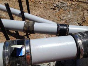
- Use a flexible thick rubber coupling to connect the decant arm and the primary spillway or discharge pipe. To provide sufficient flexibility (as required for the lower decant arm), install two couplings. Fasten the flexible coupling using strap clamps and glue. Self-tapping screws will provide added strength and robustness to the joint. Tighten steel bands with a socket rather than screwdriver and be careful to leave space between the ends of the PVC pipes within the coupling, to let the T-bar flex.
- If you are using a concrete riser decant system, angle the lower decant connection upwards so that it bisects the angle that the decant operates through. This will reduce the deformation force on the coupling.
- If you are using a concrete riser, incorporate it within the pond embankment to stop it from floating. If this is not possible, use a suitable volume of concrete ballast in the base of the manhole to prevent flotation.
- Decants should include a mechanism to allow outflows from the SRP to be temporarily stopped. This is to facilitate flocculent treatment via batch dosing and as a contingency in the event of spill or discharge of contaminants. It will allow contaminated runoff to be retained and prevent it from discharging from the site. A rope and pulley system is the best option, to lift the decants above the SRP water level. Other options such as plumbing bungs, valves or screw on end caps are also possible, depending on each specific SRP.
- Place any manhole riser or risers on a firm foundation of impervious soil.
- Lay the discharge pipe at a 1–2% gradient. Compact the fill material using a machine compactor and incorporate anti-seep collars around the pipe to increase the seepage length along the pipe, spaced at about 10 m. The vertical projection of each collar should be 500 mm, and they and their connections must be watertight.
- Don’t place pervious material such as sand or scoria around the discharge pipe or the anti-seep collars.
Following steps
- Fully stabilise the external batter face as soon as you’ve built it, according to the site’s ESC Plan, by vegetative or other means.
- Provide an all-weather access track for maintenance. Consider future maintenance – if space for desilting might be an issue, make a muck-out bund next to the forebay.
- Install and commission flocculent treatment devices.
- Certify the SRP to confirm that all design criteria have been met. Fix anything as you need to.
- Install sediment-laden diversions to direct runoff to the SRP.
Maintenance and decommissioning
When maintaining SRPs
- Inspect SRPs daily, and before and after each rainfall.
- Clean out SRPs before the amount of accumulated sediment reaches 20% of the total SRP volume. To help estimate the sediment load, mark the 20% volume height on the decant riser.
- Clean out SRPs with high capacity sludge pumps, or with excavators (long reach excavators if needed) loading onto sealed tip trucks or to a secure bunded area where the sediment can dry.
- Maintain access to the forebay at all times to allow accumulated sediment to be removed. Clean out the forebay after each runoff event if there is any evidence of sediment deposition.
- The ESC Plan should identify disposal locations for the sediment removed from the SRP. Deposit the sediment in a location that avoids direct discharge to receiving environments. Stabilise all disposal sites as required and approved in the ESC Plan. Provide all weather access for the desilting and secure bunded areas if the SRP is to operate through winter.
- Immediately repair any damage to SRPs caused by erosion or construction equipment.
When decommissioning SRPs
- Stabilise the contributing catchment or install other appropriate sediment retention devices
- Dewater the pond. Protect water quality by making sure that only clean water is discharged. Discharging dirty water from pond dewatering into a waterway is an offence and must be avoided.
- Remove and correctly dispose of all accumulated sediment.
- Remove fabric, concrete, pipe and other construction materials.
- Backfill the pond, compact soil, and re-grade as required.
- Stabilise all exposed surfaces.
Monitor performance
- Monitor the performance of SRPs by regularly checking the quality of water flowing in and out (see monitoring section on our Principles page for more information)
- Use this information to help you improve erosion control measures and the performance of the SRP
- If concentrations of suspended solids in inflows to the pond are very high, check whether your erosion control measures are effective and adapt or improve them
- Likewise, if the forebay and other parts of the pond seem to be accumulating sediment rapidly or frequently need cleaning out, then you need to assess the performance of your erosion control measures
- Reducing the sediment flowing into the pond by effective land management is the best way to achieve good water quality downstream, rather than over-relying on water treatment.
